The specific resistance of graphite electrode materials is very small. In order to obtain higher measurement accuracy, a stable current of several hundred amperes is generally required. This paper introduces the method of measuring the resistance and resistivity of the graphite electrode by using the ratio characteristic of the A/D converter. The efficient graphite electrode resistivity test method reduces the requirement for test current stability. Conducive to reducing production costs and improving the technical performance of test equipment.
Graphite Electrode Resistivity
When evaluating the quality of RP graphite electrodes used as a conductive material in ordinary power arc furnaces, resistivity is an important technical parameter. In order to reduce power loss, it is always desirable that the resistivity of the electrode material be as small as possible. The relevant standard stipulates that the difference between high-quality products and first-class products lies in whether their resistivity is less than (8.5 ~ 9.0 μΩ)·m.

Characteristics of Graphite Electrodes
The characteristics of graphite electrode materials are:
- The resistivity is small, generally only about 10μΩm;
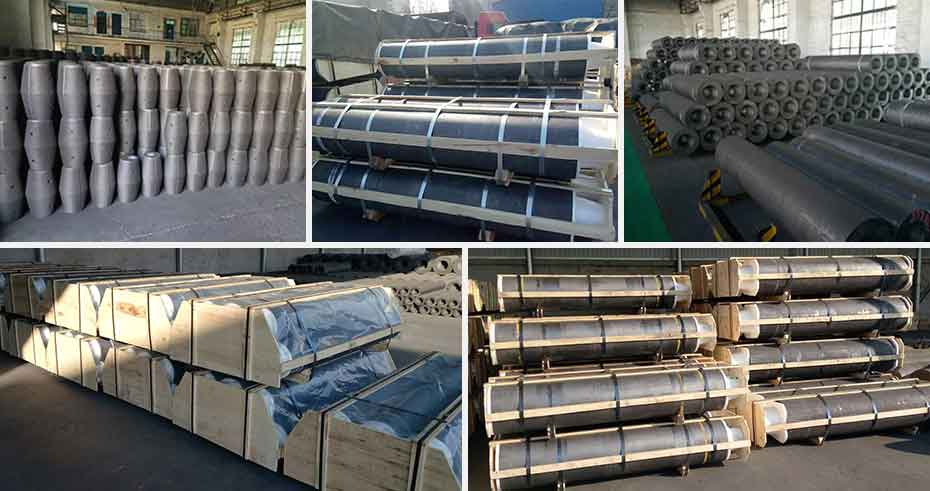
- The geometric dimensions of the finished graphite electrode are larger. Usually, the diameter is hundreds of millimeters and the length is several meters, so the resistance is very small.
If you directly measure the resistance (resistivity) of the finished graphite electrode, you need a power supply that can provide tens or even hundreds of amperes and stabilize the test current. Voltage detection equipment with higher resolution is also necessary.
Existing Test Method for Graphite Electrode Resistivity
Double bridge method.
It is suitable for the application of a small number of small samples.
Micro-ohmmeter method.
The national standard stipulates that the micro-ohmmeter method is only used for the test of the small sample resistivity in the experiment.
DC probe step-down method.
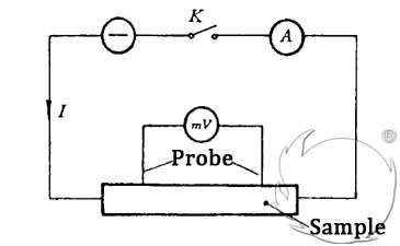
In the national standard GB6717-86 “Method for Measuring the Resistivity of Carbon Materials“, the DC probe voltage drop method as shown in the figure below is specified for large-diameter products.

Choose the distance L between the two probes according to the total length of the material being tested. And make the test current I pass along the extrusion axis of the product. Use a DC potentiometer (or millivoltmeter) to measure the voltage drop Ux between the two probes. Then the resistivity ρ of the sample is calculated as follows:
![]()
In the formula:
S represents the cross-sectional area of the product (m2);
L represents the distance (m) between the two probes.
There are some defects or deficiencies in the above methods of measuring resistivity. If a method can be found, the measurement result is not sensitive to the test current. Then, it will have a certain positive significance for simplifying the test power supply design, reducing the cost of the instrument, and improving the reliability of the instrument.
The Circuit Structure of “Dual A/D Converter”
Therefore, in some systems with microcomputers involved in the measurement of resistivity, in order to overcome the adverse effect of test current changes on the test results, the circuit structure of “dual A/D converter” is often used. That is, two sets of A/D converter circuits are used to measure U and current I respectively, and then their conversion results are simultaneously sent to a microcomputer to be calculated together with other quantities to obtain the final result. The practice has proved that this method is very effective, but more hardware is used, which increases the cost and increases the difficulty of writing software.
To Sum Up
The ratio function of the A/D converter was used to measure the resistivity of the graphite electrode material. It can eliminate the adverse effects of test current fluctuations on test results and improve test accuracy. According to need, it can be used to test the resistance or resistivity of the display sample alone, and can also be used to measure the computer system.

